Hardware Component Model
Components in Pax are inspired by components on a digital circuit board — namely: they are signal-driven, encapsulated, and composable.
We can illustrate this parallel with a virtual AndGateLED and two signal inputs (Property<T>), outputting to a VirtualLED component that lights up when the inputs are both true.
//and_gate.rs
#[pax(
    <VirtualLED signal={self.input_a && self.input_b} >
)]
pub struct AndGateLED {
    input_a: Property<bool>,
    input_b: Property<bool>,
}
This AndGateLED might be used in some other component's template like:
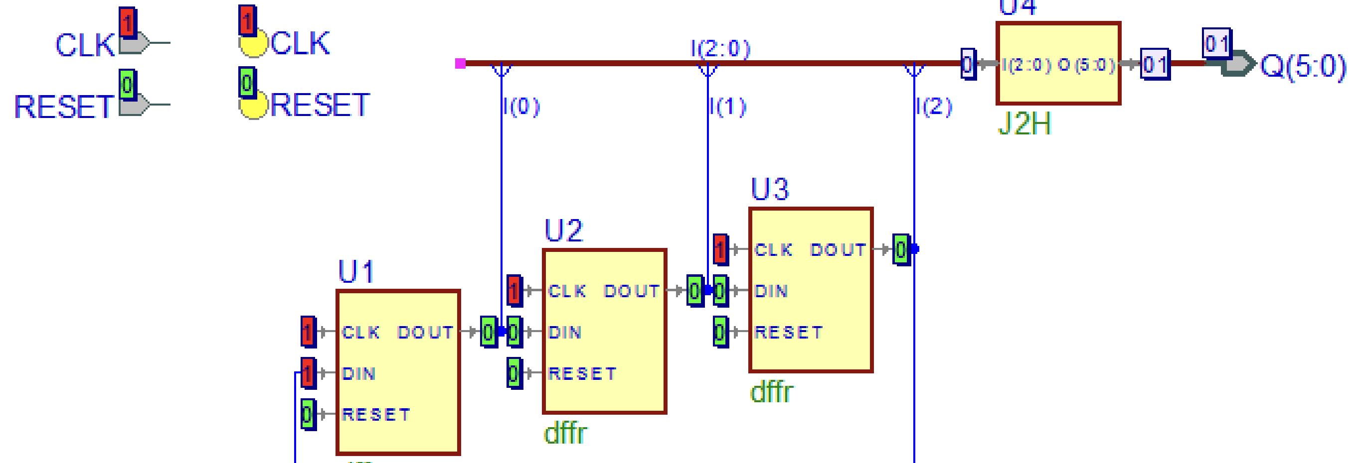
<AndGateLED input_a={self.is_validated} input_b={self.is_accepted_by_server} />While contrived, this example may look vaguely familiar if you've used a visual circuit design tool for FPGAs with VHDL or Verilog. Here's a screenshot from such a tool[1], illustrating how circuit components expose both inputs and outputs, and compose with each other for logic flow.
Looking at Pax through this lens, properties are component "inputs", while settings are component "outputs". The hierarchy of components is declared through the template of each component, traversed as a single combined tree by the Pax compiler & runtime. You can read more in the chapters Properties & Settings, Expressions, and Templates
[1] Image credit: Aldec, Inc. https://www.aldec.com/en/products/fpga_simulation/designeredition (opens in a new tab)